062 - 893 5561 | sales@bluetechcontrol.com
062 - 893 5561 | sales@bluetechcontrol.com
![]()
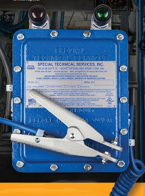
Special Technical Services’ STS 300 Series Electronic Indicating Ground System provides the highest level of worksite protection against electrostatic discharge
The STS 300 is designed for easy operation in hazardous locations where flammable fluids, vapors and dust pose a potential threat to workers, equipment and facilities.
A bright green indicator light signals a successful ground connection, while a red light will illuminate if the circuit is broken or the ground is not properly established or interrupted for any reason. The STS 300 Series Ground Indicating System can be completely integrated with your systems to stop pumps, open or close valves and to sound alarms whenever a ground is interrupted.
The rugged STS 300’s intrinsically safe monitoring circuit with grounding cable and clamp is built tough and built to last in the most challenging worksite environments.
SPECIFICATIONS:
ENGINEERING AND SERVICE
PRODUCT
BLUE TECH CONTROL CO.,LTD.
Tel 038-017127 , 062 - 893 5561
Fax 038-017127
e-mail : sales@bluetechcontrol.com